Hand-Crafting a Curved Turnout
After having completed this, I’m not entirely sure if I was brave to try it or foolhardy. But I’ve always been amazed by hand-laid turnouts (and hand-laid track in general), so for this small Z layout, I’m hand-laying all of the track. In my previous posting, I was putting down the cork roadbed. With the exception of a small bit to go on the end of the yard, the cork is down:
The only modification I made from the last post was I bought an inexpensive clothes iron, and instead of sanding I turned the iron on high heat and melted the glue flat. Much easier!
So now I can turn to the track itself. Generally what is done is you secure the complex parts of the track to the roadbed, then you tie it all together with simple track work. So you build your turnouts, crossings, crossovers, and such things first, secure them, then bring connecting track to each.
In my case, I want a couple of elegant curved turnouts by the edge of the table. If hand-laid turnouts are cool, curved hand-laid turnouts are even more so. The problem I face is, whether some might consider it cheating or not, I use and swear by Fast Tracks templates (*). I have several for HO, and for HO they have a wide variety of offerings. Crossings, crossovers, turnouts of any and every kind. But for Z, they offer just straight turnouts, from #4 to #10. No crossings, crossovers, or (gasp!) curved turnouts. So I’m on my own.
Well, not entirely. I still have the wonderful tools Fast Tracks provides for creating the points and frogs, as well as the notches in the stock rails. I also have dimensional information. If I create a typical turnout and somehow translate that into a curved turnout, the general measurements will remain the same for the same sized turnout. Flangeways, for example, or general track gauge.
That’s a good thing because, for Z, we don’t have the otherwise invaluable NMRA check tool. I do have an NZT Products clearance gauge set, and I have a nice digital Vernier caliper, so I can take measurements from a (correct) turnout created in a Fast Tracks template and then translate that to the hand-laid turnout I’m building.
I also want to get into the world of 3D printing, so I bought a copy of TurboCAD. I feel like a 3-year old driving a Ferrari with that software, but I did manage to create a reasonable diagram I can use as underlayment and a guide for the rails. It’s crude, nothing like the fantastic track guides from Fast Tracks, but it’ll get the job done. It was gratifying I was able to lay down some precise circles and get a printed version.
Anyway, enough background. If you look at the previous figure, in the lower right-hand corner you see a track splitting off the inner main, heading for the hole (and eventual bridge). I decided to start with this turnout. The curve has a 10.75” radius, and as a guess I decided the diverging rail would have a 10.0” radius. Since I use #8 turnouts off the main, it’ll have to curve a bit more strongly once it splits off, but that’s OK. It’s a siding after all.
So in TurboCAD, I gave it my best shot:
I printed this design out and sprayed the paper with a light coat of Krylon Easy-Tack. To this I overlaid wax paper, since I didn’t know if the ties would actually come off paper. Then I sprayed the wax paper with the Easy-Tack. This gives me a sticky surface onto which I can set ties yet still see rail guides underneath. (Next time I think I'll skip the wax paper...)
Speaking of ties, I cut individual turnout ties and mixed in Fast Tracks PC board ties in the appropriate spaces, which I then laid out on one of their Tie Racks. I used the branchline spacing since I knew I would be curving the tie set and would need space at the inner rail:
Once the ties were placed, I used a length of 1/8” painter’s tape to bind each tie, properly spaced, in preparation for moving onto my guide:
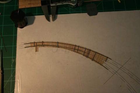
Here the ties have been transferred:
The Easy-Tack keeps them secured, and with the ties in place, I turned to creating the stock rails. I’m using Micro-Engineering Code 40 rail, which I file using a 10” mill file and a Fast Tracks Stock Aid tool. Here you see the stock rails in place along with the first point rail. The points and the frog are created using a Fast Tracks Code 40 PointForm tool:
After an embarrassing amount of time, I finally soldered all of the rails in place, checked flangeway spacing and track gauge in various places, and pulled the completed skeleton from the wax paper so I could wire brush the rail to clean off any remaining solder flux.
As I soldered rail, I verified spacing using my Vernier caliper and my mule turnout (created previously using the aforementioned Fast Tracks template). Once completed, I ran a set of trucks up and down the turnout, both ways, to see if I would have any issues at the frog. Everything seems fine, but we’ll know for sure once I run a locomotive and cars down the line. Fingers crossed.
I then applied contact glue to both the rail skeleton and the ties, allowed to dry, and then pressed the two pieces together. I re-verified gauge spacing, as I always do, even with typical turnouts built in a template. Once I was happy with alignment, I added weight to compress the rail and ties together and allowed the glue to set overnight. While I’d love nothing more than to peel this baby off the wax paper and admire the lines, I suspect all I’d do is tear the ties from the rail and generally make a mess. So the next morning I removed the weights, cut the paper around the ties (so I’d have less in the way), and then I carefully and slowly peeled the paper from the back of the ties.
I then gave the back of the ties a light wash of lacquer thinner to remove the sticky tack. While it’s true the ties will be glued to the roadbed, the underside of the throwbar tie was a gooey, sticky mess. Can’t have that, so I cleaned everything just to make sure.
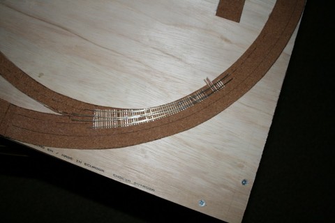
In this final image I’ve set the turnout in place. It’s not secured yet as I need to drill some holes for the throw wire and power. I also need to cut rails on either side of the frog for electrical isolation. But I wanted to show where the turnout will go, more or less (fine tuning and adjustments notwithstanding).
All in all, a gratifying project! Now all I need are three more just like it. (Actually two of those are a crossover, which I’ll save for another post…I’m waiting on some tie material…)
(*) Disclaimer: None of what I’ve written is meant to advertise for Fast Tracks. Rather, the tools are so well done and make turnout creation so much easier and repeatable it only makes sense to use the tools. As compared to RTR turnouts, on a per-turnout basis you’ll save money if you use them while creating higher quality and more effective trackwork.


